
Computerized Elevator Controls (CEC)
In-stock boards for the CEC Futura system and related Computerized Elevator Controls Corp. (CEC) equipment — SPU, EPU-COP, analog I/O, relay outputs, display interfaces, traveling cable distribution, brake/motor field, and more. Ships nationwide from Hackensack, NJ.
Available Units
Call or email with your part number to confirm stock and pricing.
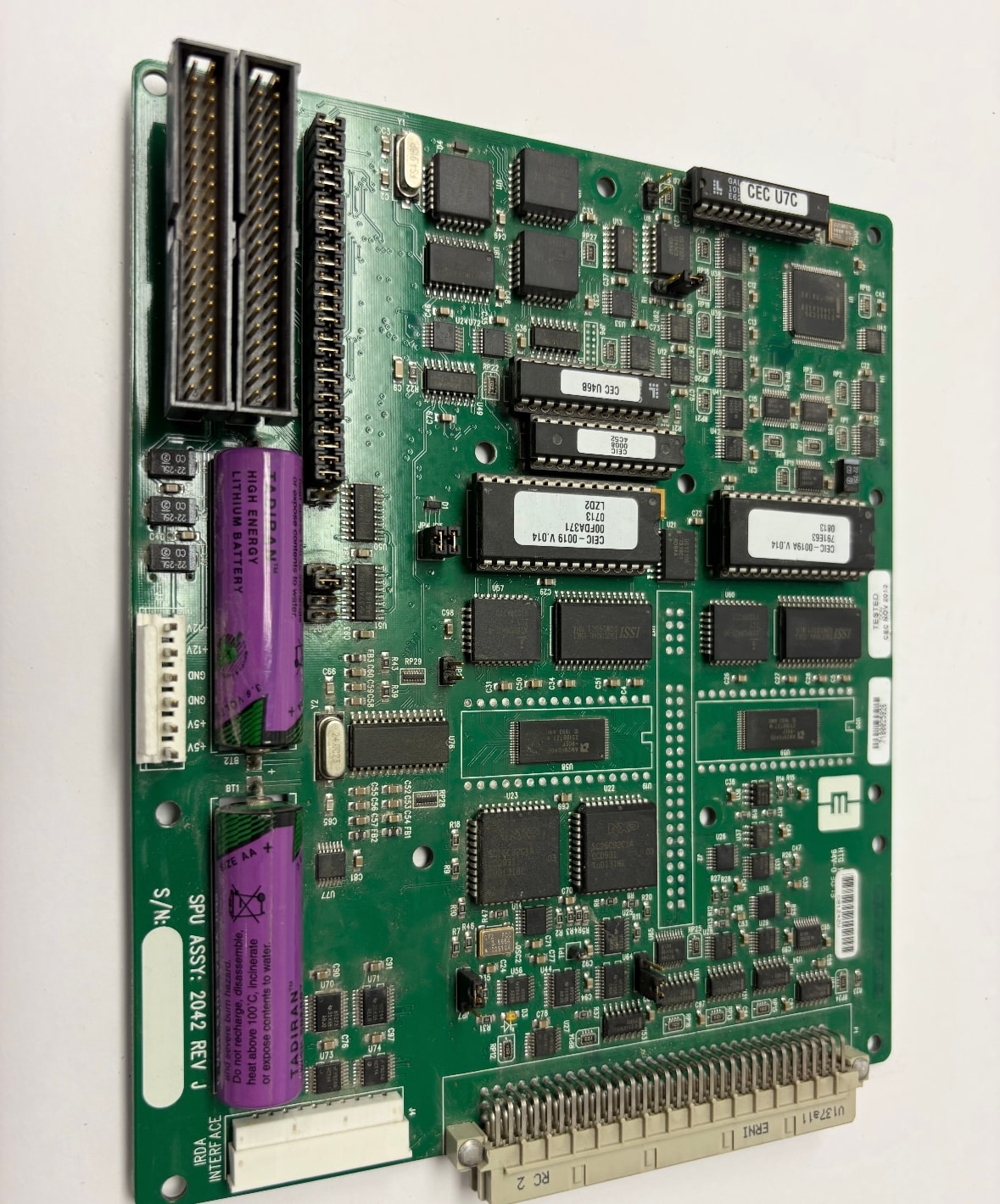
CEC (Computerized Elevator Controls Corp.)
SPU ASSY: 2042 REV J — Futura System
Signal Processing Unit — Futura Computerized Elevator Control System
- Assembly: SPU ASSY: 2042 REV J
- System: Futura Computerized Elevator Control System
- Manufacturer: Computerized Elevator Controls Corp. (CEC)
- Firmware: CEC-00194 V.014 (×2 chips)
- Firmware: CEC-00371 V.014 (CEFIC-0019 V.014)
- Battery backup: Tadiran High Energy Lithium Battery (×2)
- ICs: CEC U7C, CEC U4B8 (labeled)
- Edge connectors: dual parallel bus connectors (top)
- Bottom edge connector: ERNI UI37A11, RC 2 label
- Made in USA
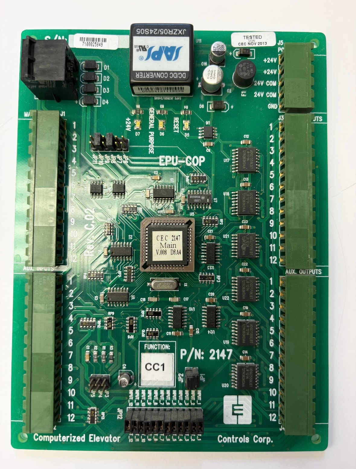
CEC (Computerized Elevator Controls Corp.)
EPU-COP — P/N: 2147 — Futura System
Car Operating Panel Processor — Futura Computerized Elevator Control System
- Part No.: 2147
- Label: EPU-COP
- Function: CC1
- System: Futura Computerized Elevator Control System
- Manufacturer: Computerized Elevator Controls Corp. (CEC)
- Main processor: CEC 2147 Main V.008 D8A4
- DC/DC Converter: SAPS JXZR05/24S05
- Terminals: AUX. INPUTS (1–12), AUX. OUTPUTS (1–12)
- Terminals: +24V (×2), 24 COM (×2), GND
- Connectors: J1 (MA), J2, J3 (OUTS), J5 (PC)
- LEDs: D1–D4 (status indicators)
- Reset button
- General Purpose header
- Tested: CEC NOV 2013
- Made in USA
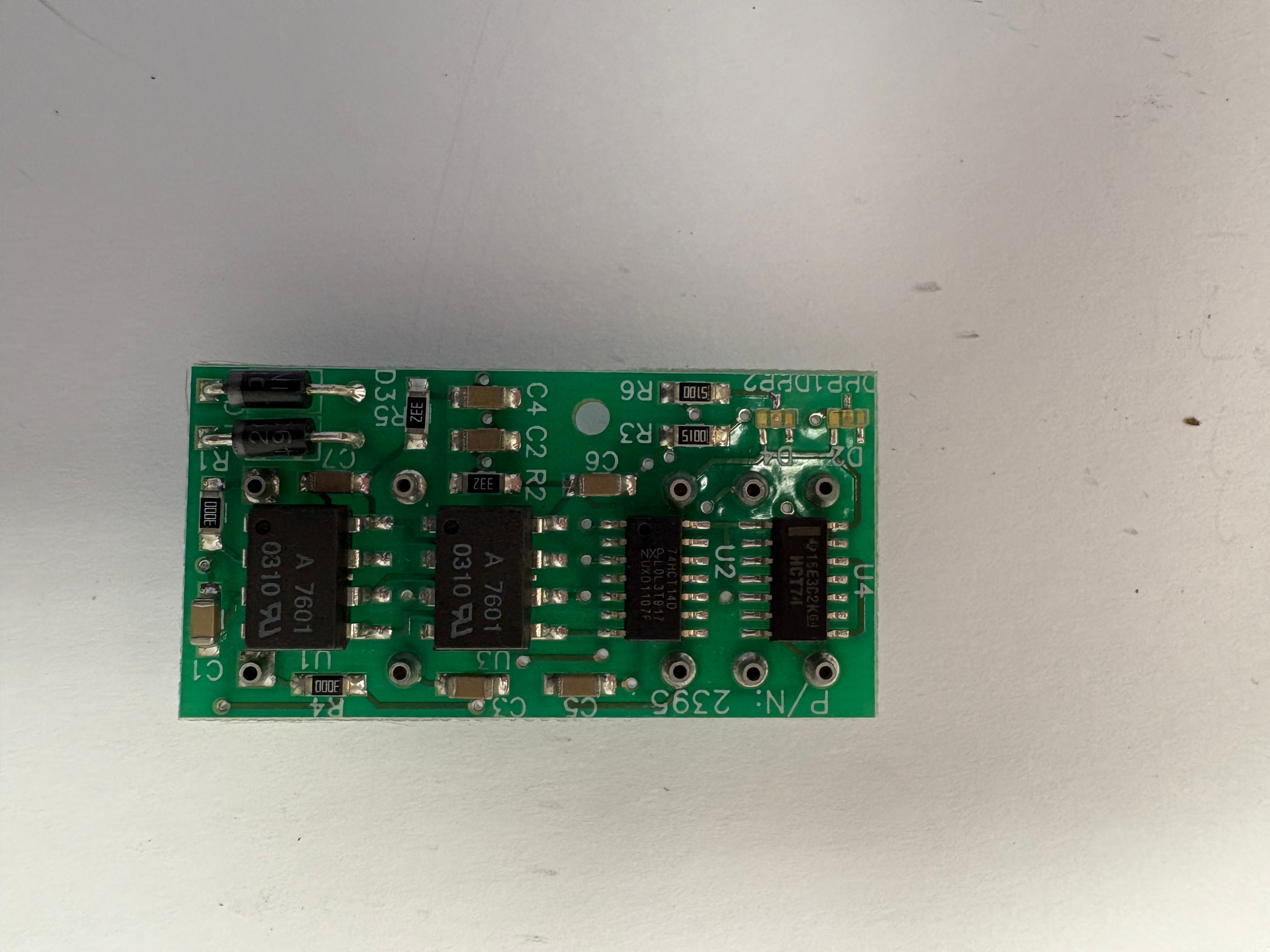
CEC
P/N: 2395
Logic / Signal Processing Board
- Part No.: 2395
- ICs: 74HCT74 (U4), 74HCT14D (U2), A7601 0310 (U3, U1)
- Diodes: D2–D4
- Resistors: R1–R6, SMD array
- Capacitors: C1–C7
- Pads: DPP1, DPP2
- Compact green PCB form factor
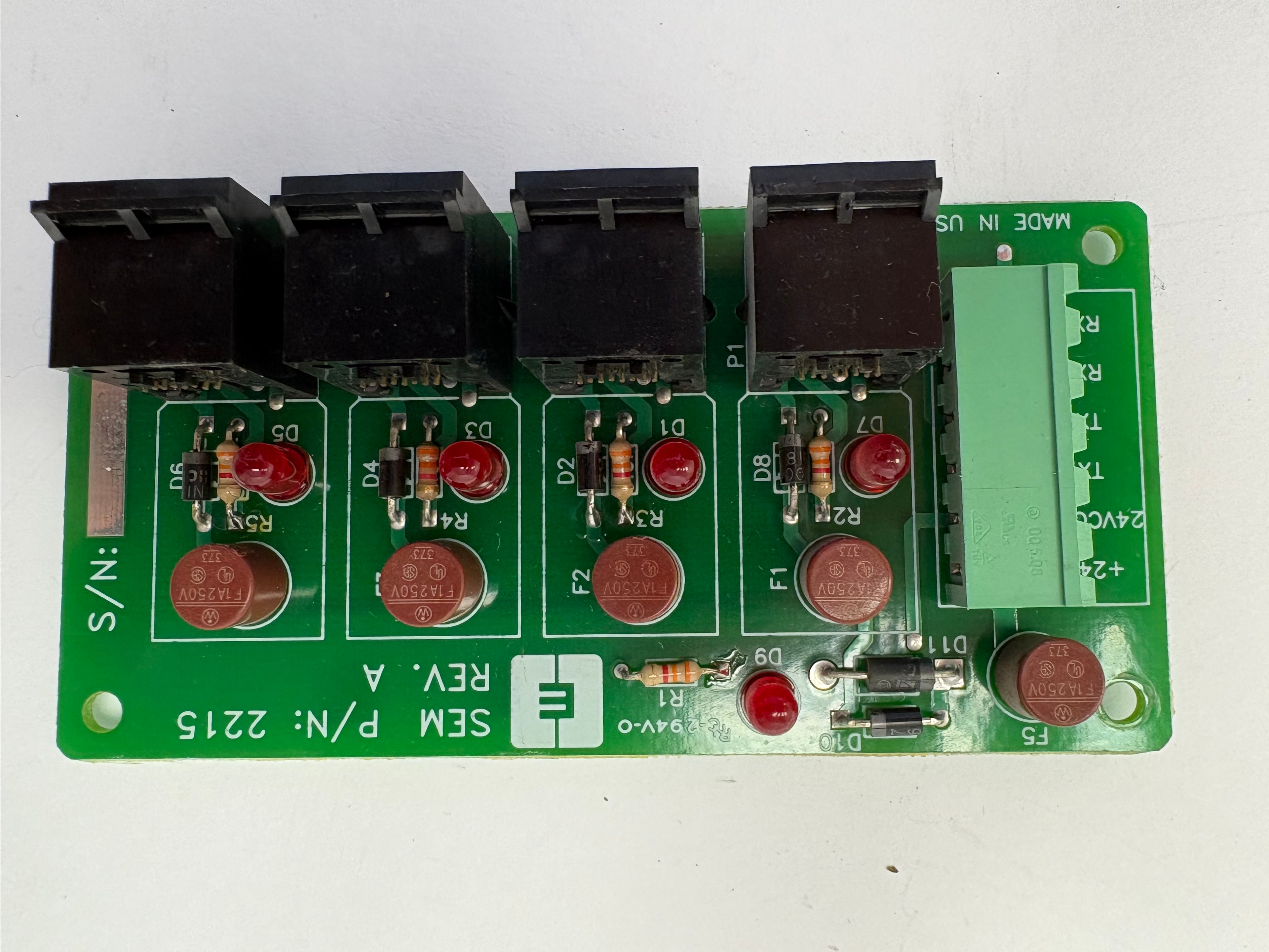
SEM
P/N: 2215
Relay Output Board
- Part No.: 2215
- Revision: REV. A
- Made in USA
- Fuses: F1–F5, F1A 250V (×5)
- Relay sockets: P1–P4 (4 channels)
- Indicators: D1–D8 red LEDs per channel
- Resistors: R1–R5 per channel
- Diodes: D9–D11
- Terminals: +24V, 24VCOM, TX+, TX−, RX+, RX−
- Green push-in terminal block (left edge)
- S/N label on right edge
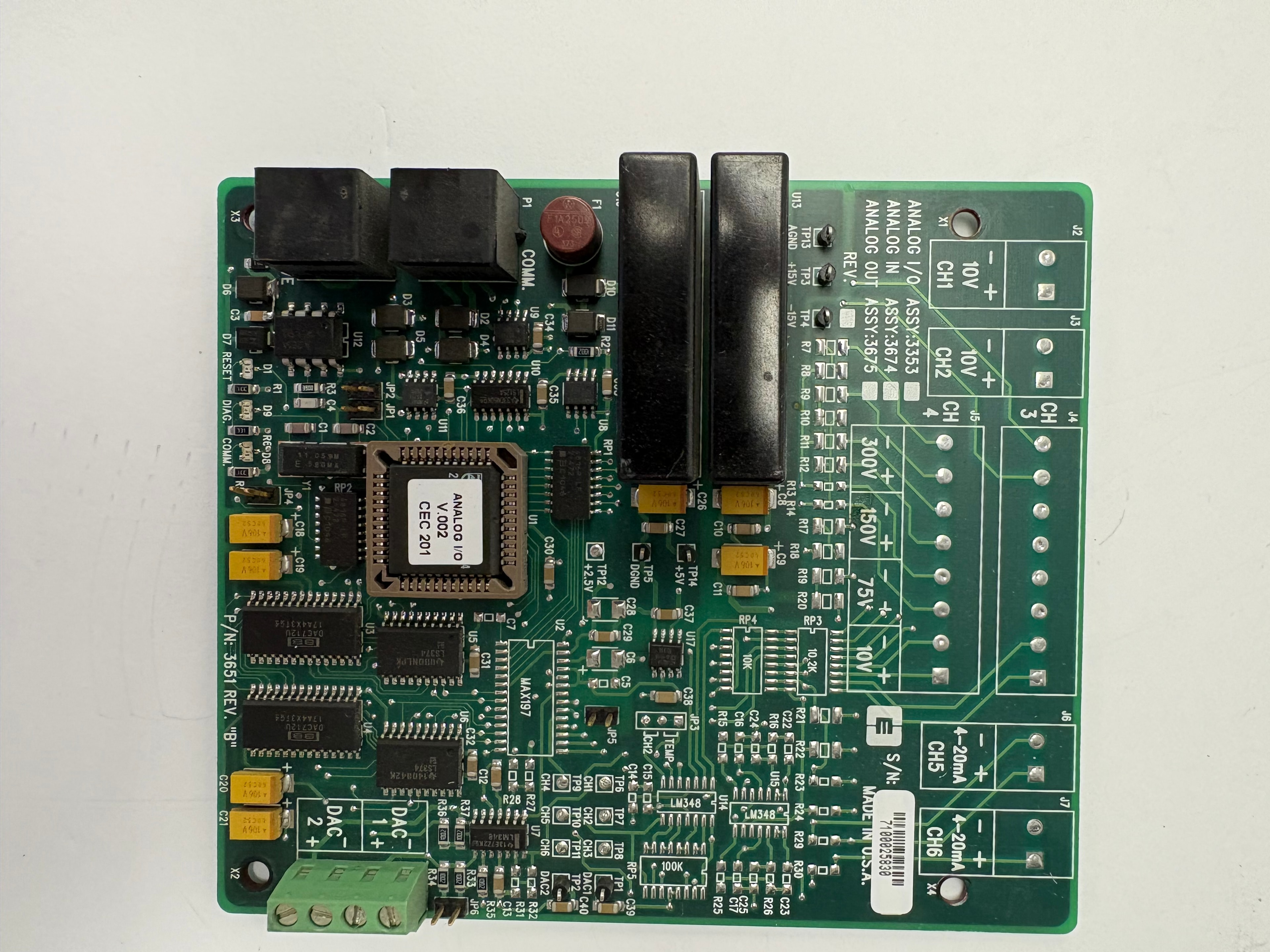
CEC
P/N: 3651
Analog I/O Board
- Part No.: 3651 REV. "B"
- S/N: 7100025830
- Made in USA
- ASSY: 3353 (Analog I/O), 3674 (Analog IN), 3675 (Analog OUT)
- ADC: MAX197
- Op-amp: LM346
- DAC outputs: DAC1, DAC2
- Analog inputs: CH1–CH4 (±10V), CH5 (4–20mA), CH6 (4–20mA)
- Voltage ranges: ±10V, 75V, 150V, 300V
- Connectors: J2–J7, X1, X2 (green screw terminals)
- Test points: TP1–TP15
- Trim pots: RP1–RP8
- Backplane connectors: P1 (dual black edge)
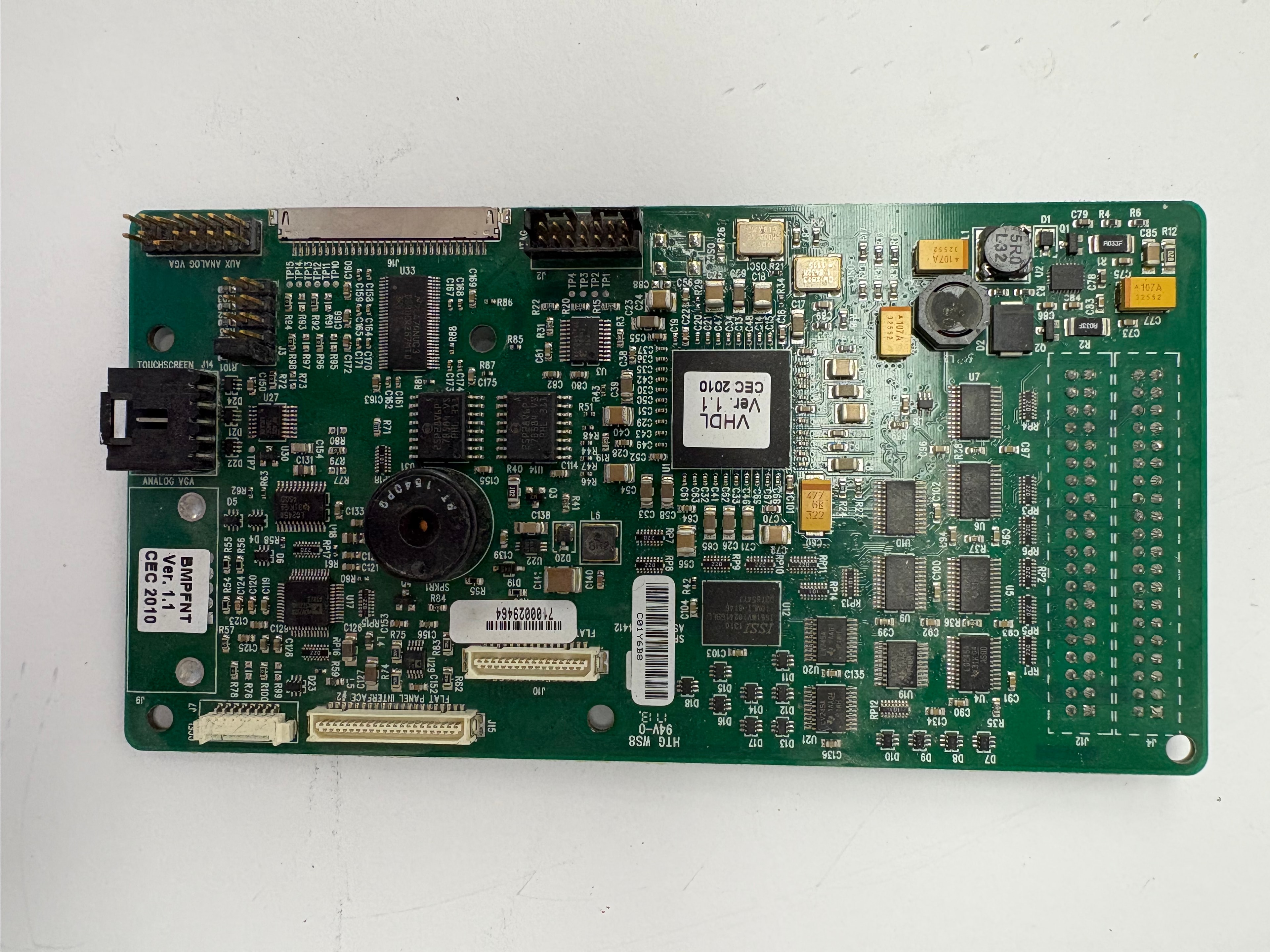
CEC
BMPFNT Ver. 1.1
Front Panel / Display Interface Board
- Part No.: BMPFNT
- Version: Ver. 1.1 — CEC 2010
- S/N: 7100029464
- PCB: HTG WS8 94V-0
- FPGA firmware: VHDL Ver. 1.1 CEC 2010
- Memory: ISSI IS61WV25616BLL
- Flat Panel Interface: J5, J10 (ribbon connectors)
- Touchscreen connector: J14
- AUX ANALOG VGA connector (right edge)
- ANALOG VGA connector
- Speaker: SPKR1
- Connectors: J1–J16, JP1–JP6
- Trim pots: RP1–RP13
- Reset button: D7
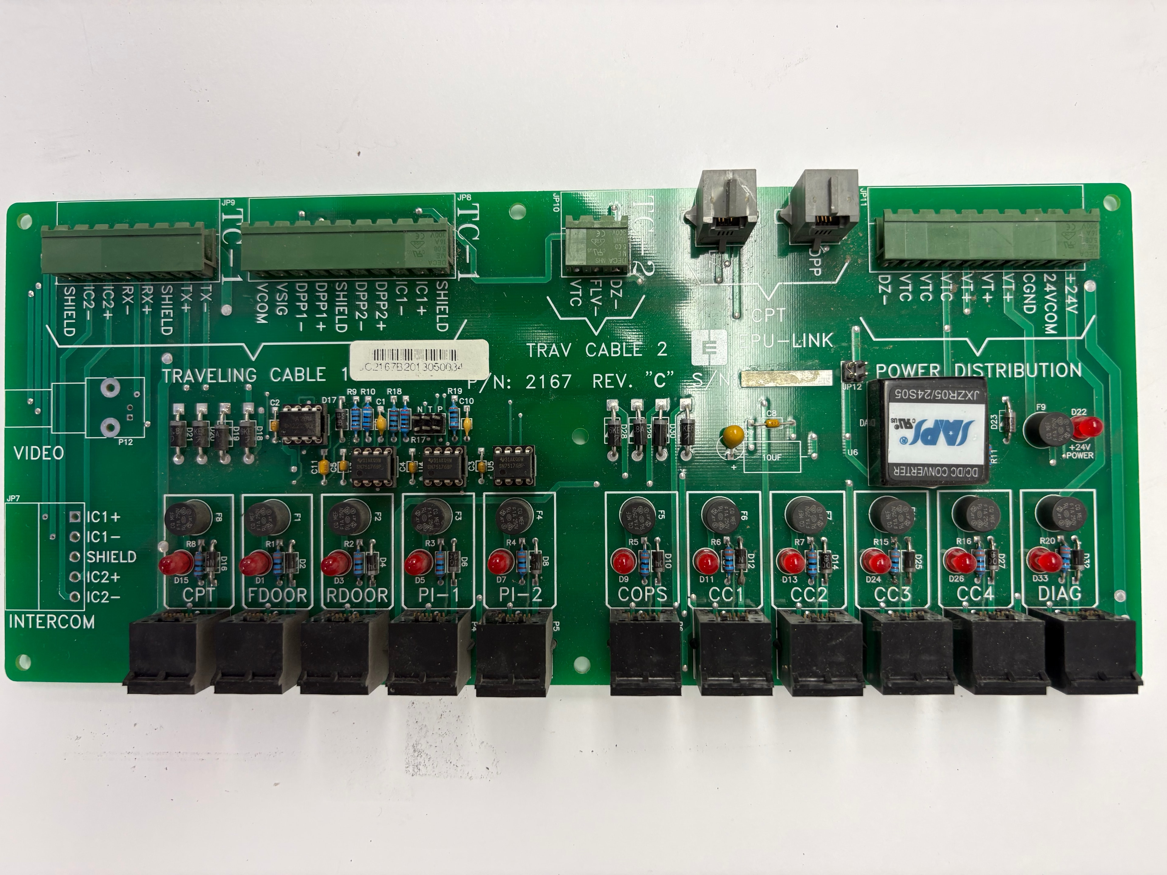
CEC
P/N: 2167
Car Top / Traveling Cable Distribution Board
- Part No.: 2167
- Revision: REV. "C"
- DC/DC Converter: SAPS JXZR05/24S05
- Relay array: 10 relay sockets (top row)
- LED indicators: D1–D33 (red, per relay)
- Fuses: F3–F9
- Terminals (top): DIAG, CC4, CC3, CC2, CC1, COPS, PI-2, PI-1, RDOOR, FDOOR, CPT
- Terminals (right): INTERCOM (IC1+/−, IC2+/−, SHIELD), VIDEO
- Traveling Cable 1 (TC-1): SHIELD, C1+/−, DPP2+/−, DPP1+/−, VSIG, VCOM, TX+/−, RX+/−, IC2+/−, SHIELD
- Traveling Cable 2 (TC-2): DZ−, FLV−, VTC
- CPU-LINK connector: JP10
- Power Distribution: +24V, 24VCOM, CGND, VT+/−, VTC, DZ−
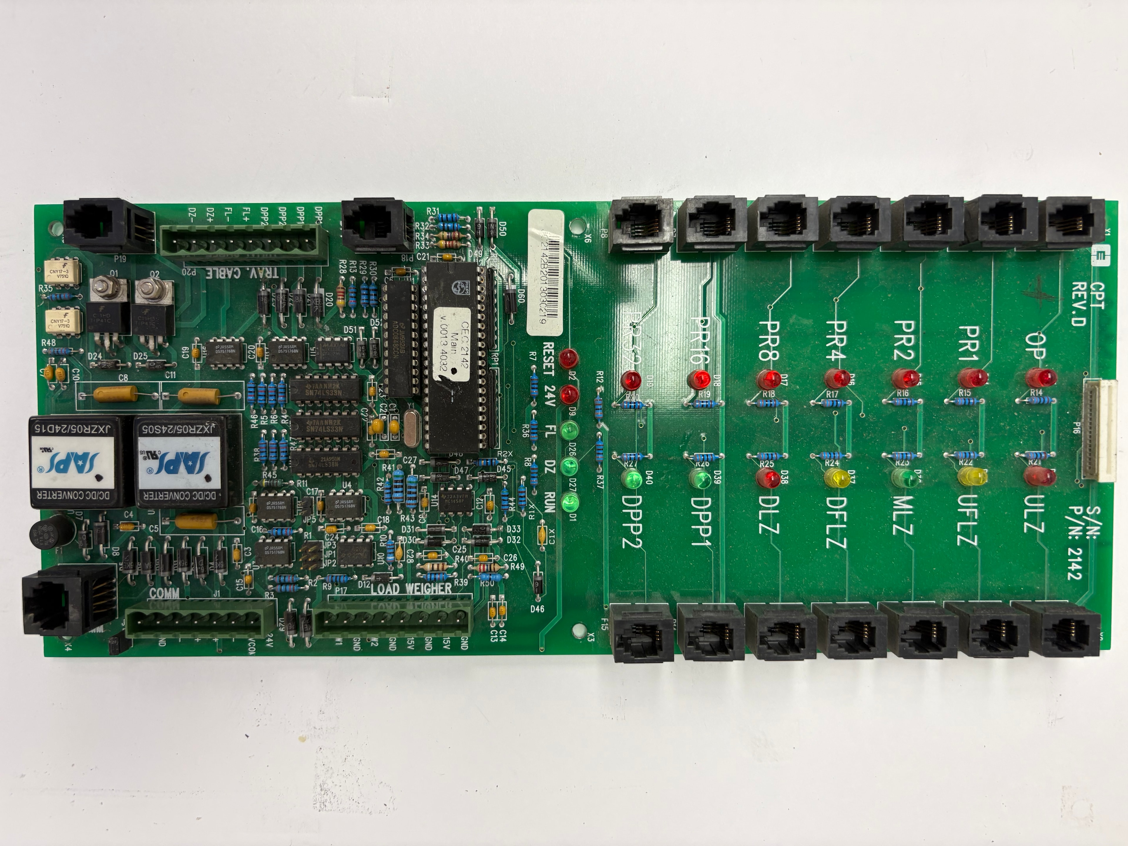
CEC
CPT — P/N: 2142
Car Position / Leveling Board
- Part No.: 2142
- Revision: CPT REV. D
- DC/DC Converters: SAPS JXZR05/24S05 + JXZR05/24D15 (×2)
- Firmware: CEC V.001 40302
- LED indicators: OP, PR1, PR2, PR4, PR8, PR16 (red)
- Zone indicators: ULZ (yellow), UFLZ (yellow), MLZ (green), DFLZ (yellow), DLZ (yellow)
- Door/position: DPP1 (green), DPP2 (green)
- Status: RUN (green), DZ (green), FL (green), RESET 24V (red)
- Load Weigher section
- COMM connector
- Traveling Cable: TRAV. CABLE P20
- Terminals: DPP+/−, FL+/−, DZ+/−
- RJ45 connectors: top and bottom rows
CEC / Futura
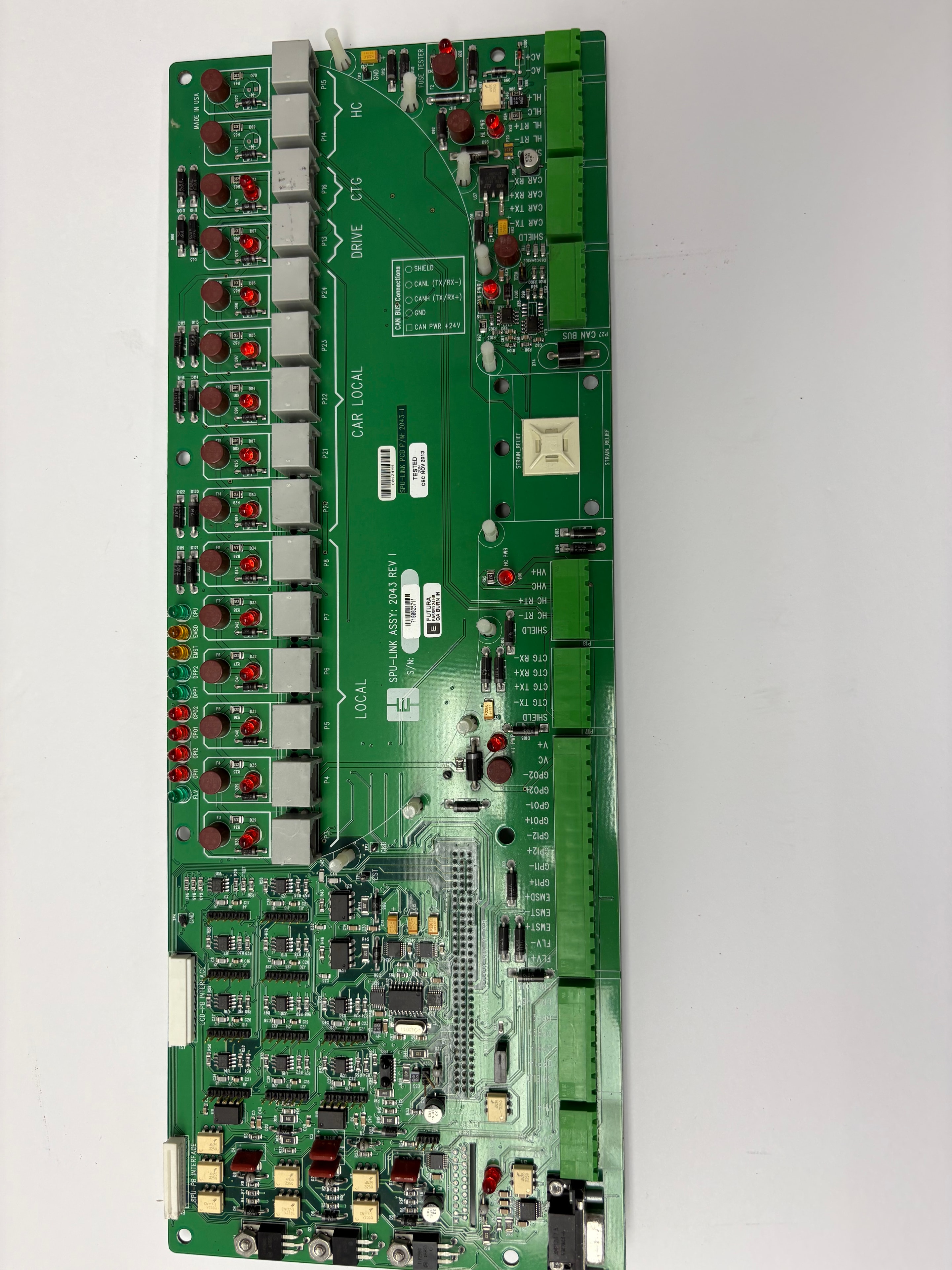
SPU-Link — ASSY: 2043
Serial Processing Unit Link Board
- Part No.: PCB P/N 2043-1
- Assembly: SPU-LINK ASSY: 2043 REV I
- S/N: 7100025111
- Manufactured: CEC NOV 2012 — FUTURA
- Made in USA
- Sections: LOCAL, CAR LOCAL, DRIVE, CTG, HC
- CAN BUS connections section
- STRAIN RELAY section
- Interfaces: SPU-PB INTERFACE, CD-PB INTERFACE
- Terminals: GPO1+/−, GPO2+/−, GPI1, GPI2, EMS1, EMS2, FL+/−, V4, VC
- CTC: TX+, RX+, RX−, SHIELD
- HC: VHC, RC, RT+/−
- LED indicators: red (multiple rows)
- Connectors: P3–P26 (RJ45 top and bottom)
CEC
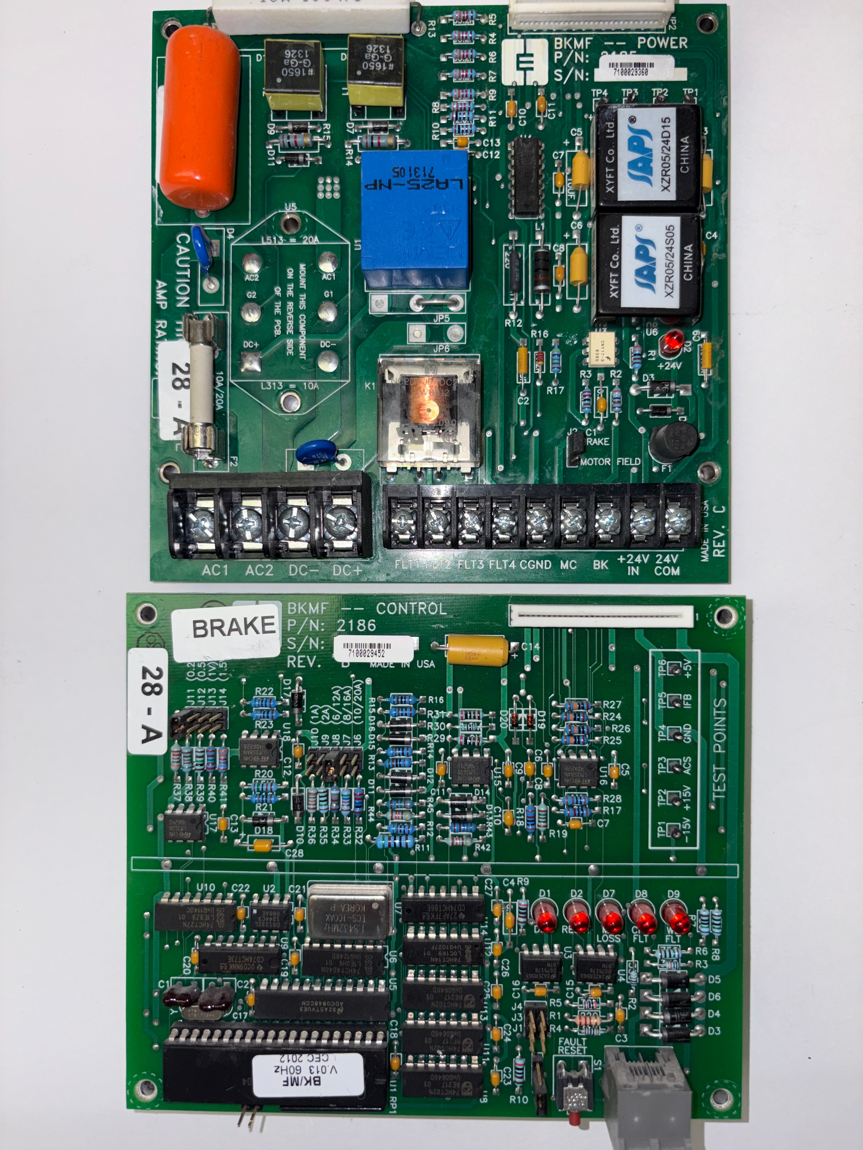
BKMF — P/N: 2186
Brake / Motor Field Control / Logic Board
- Part No.: 2186
- Revision: REV. C
- Made in USA
- Firmware label: BK/MF V.013 60Hz CEC 2012
- ICs: U1–U19 (logic array)
- Resistor pack: RP1
- LED indicators: D1–D9 (red, top row), D10–D20 (status row)
- Test points: +5V (TP6), IFB (TP5), GND (TP4), AC5 (TP3), +15V (TP2), −15V (TP1)
- Fault Reset switch: S1
- Resistors: R1–R45
- Capacitors: C1–C28
- Edge connector: right side (backplane interface)
- Set label: 28 – A
- Companion board to BK-MF POWER P/N 2185
CEC
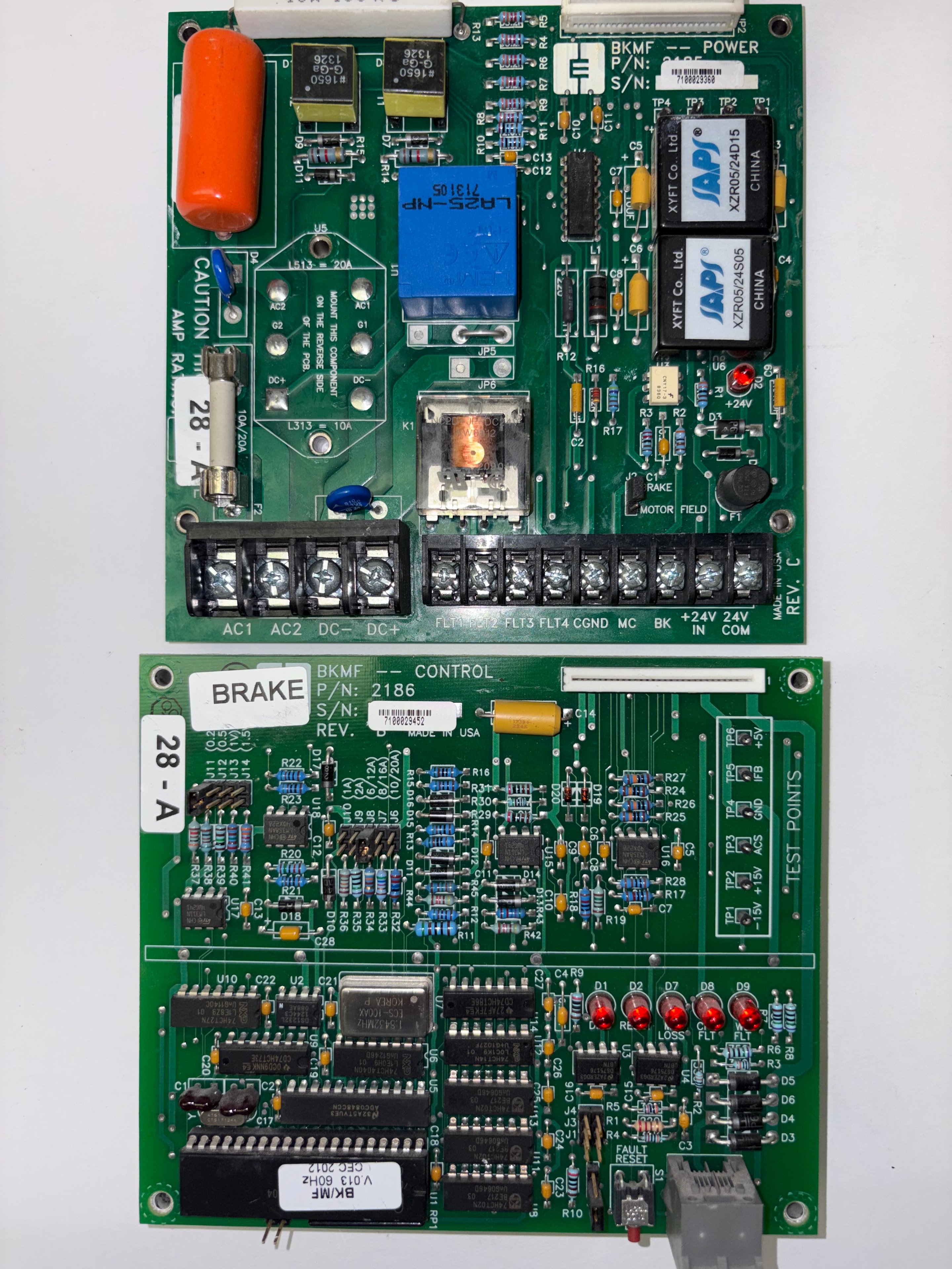
BK-MF POWER — P/N: 2185
Brake / Motor Field Power Board
- Part No.: 2185
- Label: BK-MF POWER
- Made in USA
- DC/DC Converters: SAPS XZR05/24S05 + XZR05/24D15
- Current sensor: LR25-NP
- Relay: K1
- Fuses: F1, F2 (10A/20A)
- Terminals: POWER, MOTOR FIELD, BRAKE
- Terminals: AC1, AC2, DC−, DC+, FLT1–FLT4, CGND, MC, BK, +24V, IN, COM
- Note on PCB: "MOUNT THIS COMPONENT ON THE REVERSE SIDE OF THE PCB"
- Green screw terminal blocks (top and right edges)
- Companion board to BKMF P/N 2186 control/logic board
CEC
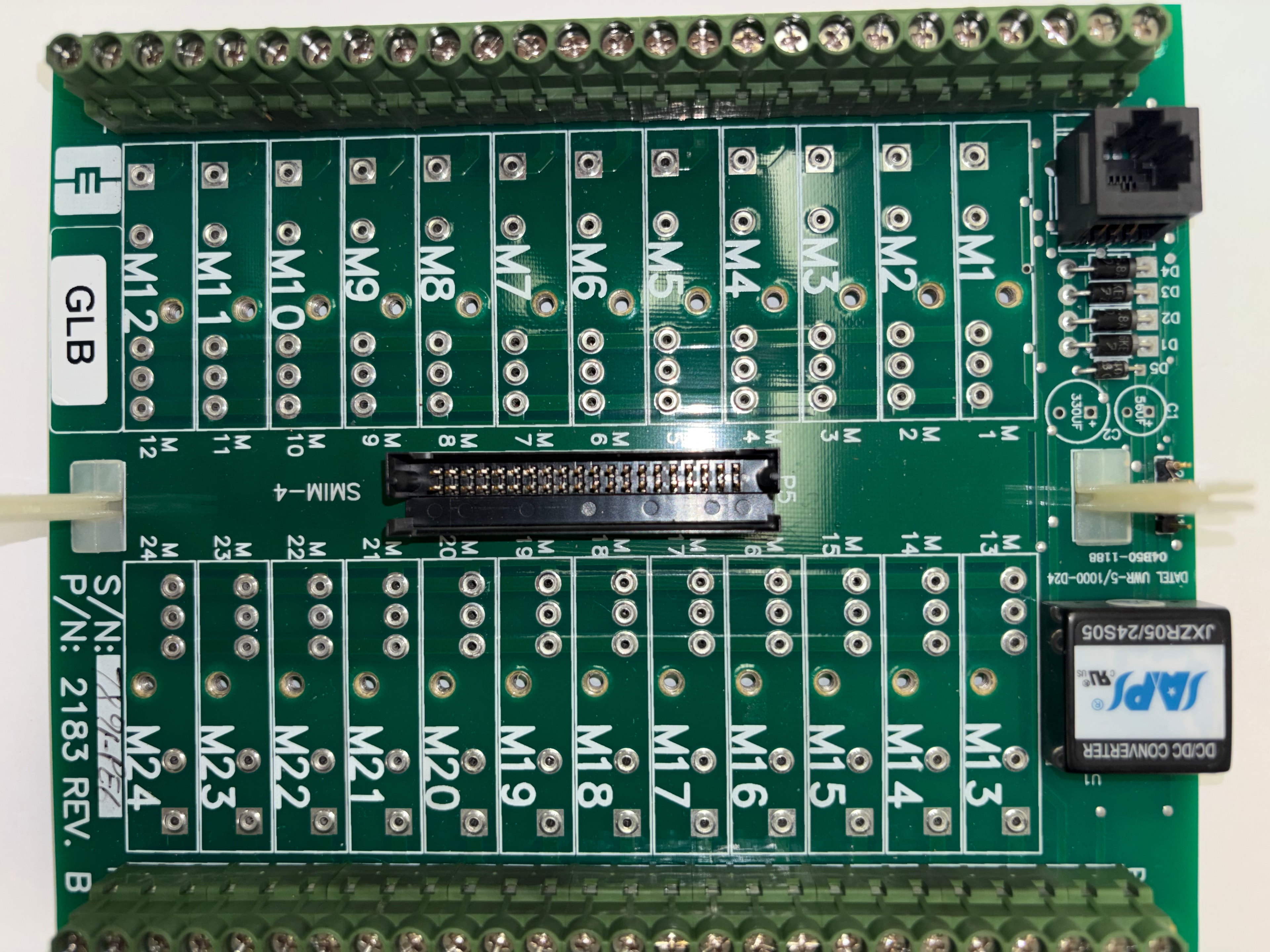
P/N: 2183
Motor Interface / Terminal Board
- Part No.: 2183
- Revision: REV. B
- Label: GLB
- DC/DC Converter: SAPS JXZR05/24S05 (U1)
- DC/DC Converter: DATEL UWR-5/1000-D24 (04B50-1188)
- Terminal groups: M1–M12 (lower row), M13–M24 (upper row)
- Bus connector: SMIM-4 (P5)
- LED indicators: D1–D5
- Capacitors: C1 (560µF), C2 (330µF)
- Green screw terminal blocks — top and bottom edges
- RJ11 connector (bottom left)
CEC
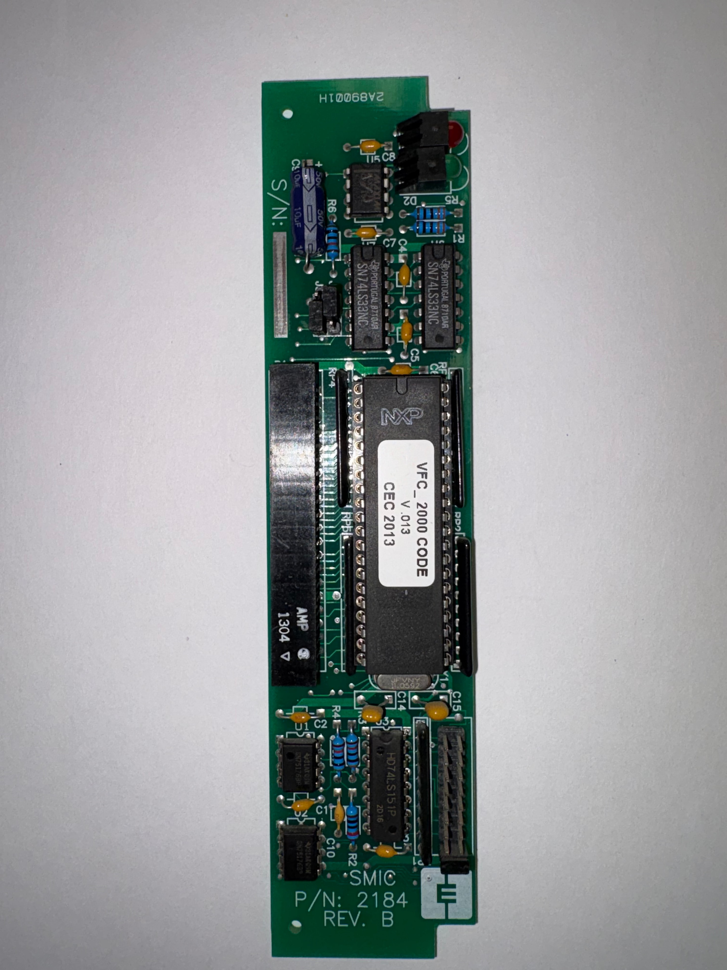
SMIC — P/N: 2184
Speed / Motor Interface Card
- Part No.: 2184
- Revision: REV. B
- Label: SMIC
- S/N: 2AB9001H
- Firmware: VFC_2000 CODE V.013 — CEC 2013 (NXP EPROM)
- ICs: SN74LS33NC (×2, Portugal 8710AR), HD74LS151P (2D16)
- AMP: 1304
- Resistor packs: RP4, R2, R4, R6
- Capacitors: C4, C5, C8, C10, C14, C15
- Connectors: J3, edge connectors (both ends)
- Slim card form factor
Key features
- P/N 2395: logic/signal processing board for CEC elevator control systems
- SEM P/N 2215: 4-channel relay output board with LED indicators and fuse protection
- P/N 3651: analog I/O board — 4–20mA outputs, ±10V/75V/150V/300V analog inputs
- BMPFNT Ver. 1.1: front panel display interface with VHDL FPGA, touchscreen, and VGA outputs
- P/N 2167: car top traveling cable distribution board — relay array, power distribution, intercom, video
- CPT P/N 2142: car position and leveling board — zone LEDs, load weigher, traveling cable interface
- SPU-Link 2043: serial processing unit link board — CAN BUS, drive, CTG, HC, and car local sections
- BKMF P/N 2186: brake/motor field control/logic board — BK/MF V.013 60Hz CEC 2012, test points TP1–TP6, fault reset S1
- BK-MF POWER P/N 2185: brake/motor field power board — SAPS DC/DC converters, LR25-NP current sensor, K1 relay, BRAKE/MOTOR FIELD/POWER terminals
- P/N 2183: M1–M24 motor terminal board with SMIM-4 bus connector
- SMIC P/N 2184: speed/motor interface card with VFC_2000 firmware
- 1-year warranty on all units sold
1-Year Warranty
All computerized elevator control boards sold by Gemini Elevator Service carry a full 1-year warranty. We also repair CEC and Futura PCBs — send us your failed unit for a quote.
Learn about board repairGet in touch
Call or email with your part number and we'll confirm availability.
(201) 250-8083info@geminielevatorservice.comNeed other boards or elevator parts?
Browse our full in-stock boards inventory or the complete parts catalog — tape guides, relays, power supplies, drives, and more.